
SKYSPIN
Solutions: We will first obtain ε-closures of q0, q1 and q2 as follows:

Now the δ' transition on each input symbol is obtained as:

Now the δ' transition on q1 is obtained as:

The δ' transition on q2 is obtained as:

Now we will summarize all the computed δ' transitions:

The transition table can be:

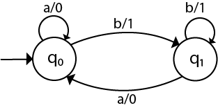
State q1 and q2 become the final state as ε-closure of q1 and q2 contain the final state q2. The NFA can be shown by the following transition diagram:
Superficially it would appear that deterministic and non-deterministic finite state automata are entirely separate beasts. It turns out, however, that they are equivalent. For any language recognized by an NFA, there exists a DFA that recognizes that language and vice versa. The algorithm to make the conversion from NFA to DFA is relatively simple, even if the resulting DFA is considerably more complex than the original NFA. After the jump I will prove this equivalence and also step through a short example of converting an NFA to an equivalent DFA.
Let, M = (Q, ∑, δ, q0, F) is an NFA which accepts the language L(M). There should be equivalent DFA denoted by M' = (Q', ∑', q0', δ', F') such that L(M) = L(M').
Step 2: Add q0 of NFA to Q'. Then find the transitions from this start state.
Step 3: In Q', find the possible set of states for each input symbol. If this set of states is not in Q', then add it to Q'.
Step 4: In DFA, the final state will be all the states which contain F(final states of NFA)
Solution: For the given transition diagram we will first construct the transition table.

Now we will obtain δ' transition for state q0.

The δ' transition for state q1 is obtained as:

The δ' transition for state q2 is obtained as:

Now we will obtain δ' transition on [q1, q2].

The state [q1, q2] is the final state as well because it contains a final state q2. The transition table for the constructed DFA will be:

The Transition diagram will be:
The state q2 can be eliminated because q2 is an unreachable state.
Solution: For the given transition diagram we will first construct the transition table.

Now we will obtain δ' transition for state q0.

The δ' transition for state q1 is obtained as:

Now we will obtain δ' transition on [q0, q1].

Similarly,

As in the given NFA, q1 is a final state, then in DFA wherever, q1 exists that state becomes a final state. Hence in the DFA, final states are [q1] and [q0, q1]. Therefore set of final states F = {[q1], [q0, q1]}.
The transition table for the constructed DFA will be:

The Transition diagram will be:
Even we can change the name of the states of DFA.
Suppose

With these new names the DFA will be as follows:
Where

NFA with ∈ move: If any FA contains ε transaction or move, the finite automata is called NFA with ∈ move.
ε-closure: ε-closure for a given state A means a set of states which can be reached from the state A with only ε(null) move including the state A itself.
Step 2: Find the states for each input symbol that can be traversed from the present. That means the union of transition value and their closures for each state of NFA present in the current state of DFA.
Step 3: If we found a new state, take it as current state and repeat step 2.
Step 4: Repeat Step 2 and Step 3 until there is no new state present in the transition table of DFA.
Step 5: Mark the states of DFA as a final state which contains the final state of NFA.
Solution:
Let us obtain ε-closure of each state.

Now, let ε-closure {q0} = {q0, q1, q2} be state A.
Hence

The partial DFA will be
Now,

For state C:

The DFA will be,
 Solution: Let us obtain the ε-closure of each state.

Now we will obtain δ' transition. Let ε-closure(q0) = {q0, q1, q2} call it as state A.
 Thus we have obtained

The partial DFA will be:
Now we will find the transitions on states B and C for each input.
Hence
 Thus we have obtained

The partial transition diagram will be
Now we will obtain transitions for C:

Hence the DFA is
As A = {q0, q1, q2} in which final state q2 lies hence A is final state. B = {q1, q2} in which the state q2 lies hence B is also final state. C = {q2}, the state q2 lies hence C is also a final state.
We have to follow the various steps to minimize the DFA. These are as follows:
Step 1: Remove all the states that are unreachable from the initial state via any set of the transition of DFA.
Step 2: Draw the transition table for all pair of states.
Step 3: Now split the transition table into two tables T1 and T2. T1 contains all final states, and T2 contains non-final states.
Step 4: Find similar rows from T1 such that:

That means, find the two states which have the same value of a and b and remove one of them.
Step 5: Repeat step 3 until we find no similar rows available in the transition table T1.
Step 6: Repeat step 3 and step 4 for table T2 also.
Step 7: Now combine the reduced T1 and T2 tables. The combined transition table is the transition table of minimized DFA.
Solution:
Step 1: In the given DFA, q2 and q4 are the unreachable states so remove them.
Step 2: Draw the transition table for the rest of the states.

Step 3: Now divide rows of transition table into two sets as:
1. One set contains those rows, which start from non-final states:

2. Another set contains those rows, which starts from final states.

Step 4: Set 1 has no similar rows so set 1 will be the same.
Step 5: In set 2, row 1 and row 2 are similar since q3 and q5 transit to the same state on 0 and 1. So skip q5 and then replace q5 by q3 in the rest.

Step 6: Now combine set 1 and set 2 as:

Now it is the transition table of minimized DFA.

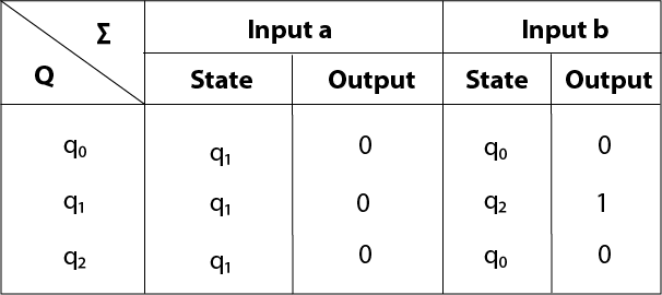
Transition table for Moore Machine is:
In the above Moore machine, the output is represented with each input state separated by /. The output length for a Moore machine is greater than input by 1.
Input: 010
Transition: δ (q0,0) => δ(q1,1) => δ(q1,0) => q2
Output: 1110(1 for q0, 1 for q1, again 1 for q1, 0 for q2)
Solution: To generate 1's complement of a given binary number the simple logic is that if the input is 0 then the output will be 1 and if the input is 1 then the output will be 0. That means there are three states. One state is start state. The second state is for taking 0's as input and produces output as 1. The third state is for taking 1's as input and producing output as 0.
Hence the Moore machine will be,
For instance, take one binary number 1011 then

Thus we get 00100 as 1's complement of 1011, we can neglect the initial 0 and the output which we get is 0100 which is 1's complement of 1011. The transaction table is as follows:
Thus Moore machine M = (Q, q0, ∑, O, δ, λ); where Q = {q0, q1, q2}, ∑ = {0, 1}, O = {0, 1}. the transition table shows the δ and λ functions.
Solution: For designing such a machine, we will check two conditions, and those are 101 and 110. If we get 101, the output will be A, and if we recognize 110, the output will be B. For other strings, the output will be C.
The partial diagram will be:
Now we will insert the possibilities of 0's and 1's for each state. Thus the Moore machine becomes:
Solution:
The Moore machine will be:
 This is the required Moore machine. In this machine, state q1 accepts
an odd number of 1's and state q0 accepts even number of 1's. There is
no restriction on a number of zeros. Hence for 0 input, self-loop can be
applied on both the states.
This is the required Moore machine. In this machine, state q1 accepts
an odd number of 1's and state q0 accepts even number of 1's. There is
no restriction on a number of zeros. Hence for 0 input, self-loop can be
applied on both the states.
Solution:
The Moore machine will be:

Solution: For designing such a machine, we will check two conditions, and those are 101 and 110. If we get 101, the output will be A. If we recognize 110, the output will be B. For other strings the output will be C.
The partial diagram will be:
Now we will insert the possibilities of 0's and 1's for each state. Thus the Mealy machine becomes:
Solution: The mealy machine will be:

The following steps are used for converting Mealy machine to the Moore machine:
Step 1: For each state(Qi), calculate the number of different outputs that are available in the transition table of the Mealy machine.
Step 2: Copy state Qi, if all the outputs of Qi are the same. Break qi into n states as Qin, if it has n distinct outputs where n = 0, 1, 2....
Step 3: If the output of initial state is 0, insert a new initial state at the starting which gives 1 output.
 Solution:
Transition table for above Mealy machine is as follows:
Transition diagram for Moore machine will be:
 Solution:
Transition table for above Mealy machine is as follows:
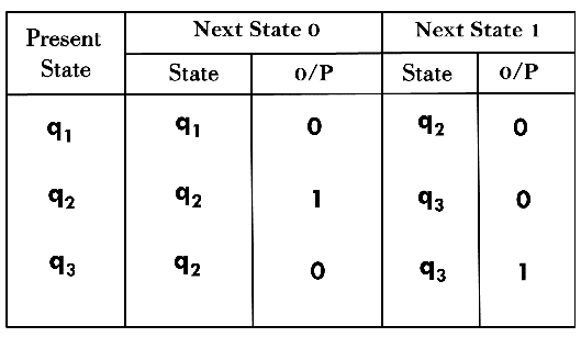 The state q1 has only one output. The state q2 and q3 have both
output 0 and 1. So we will create two states for these states. For q2,
two states will be q20(with output 0) and q21(with output 1). Similarly,
for q3 two states will be q30(with output 0) and q31(with output 1).
The state q1 has only one output. The state q2 and q3 have both
output 0 and 1. So we will create two states for these states. For q2,
two states will be q20(with output 0) and q21(with output 1). Similarly,
for q3 two states will be q30(with output 0) and q31(with output 1).
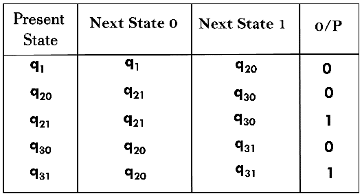
Transition table for Moore machine will be:
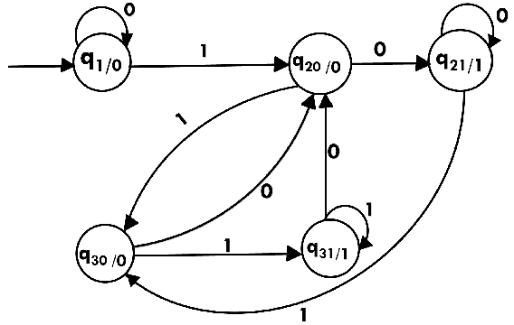
 Transition diagram for Moore machine will be:
We cannot directly convert Moore machine to its equivalent Mealy machine because the length of the Moore machine is one longer than the Mealy machine for the given input. To convert Moore machine to Mealy machine, state output symbols are distributed into input symbol paths. We are going to use the following method to convert the Moore machine to Mealy machine.

Solution:
The transition table of given Moore machine is as follows:

The equivalent Mealy machine can be obtained as follows:


Hence the transition table for the Mealy machine can be drawn as follows:
The equivalent Mealy machine will be,
Solution:
The transition table of given Moore machine is as follows:

The equivalent Mealy machine can be obtained as follows:

The λ for state q1 is as follows:

The λ for state q2 is as follows:

Hence the transition table for the Mealy machine can be drawn as follows:
The equivalent Mealy machine will be,

Solution:
The transaction diagram for the given problem can be drawn as:
The equivalent Mealy machine can be obtained as follows:

The λ for state q1 is as follows:

The λ for state q2 is as follows:

Hence the transition table for the Mealy machine can be drawn as follows:
The equivalent Mealy machine will be,
UNIT-1 (CHAPTER-2 FINITE AUTOMATA)
Eliminating ε Transitions
NFA with ε can be converted to NFA without ε, and this NFA without ε can be converted to DFA. To do this, we will use a method, which can remove all the ε transition from given NFA. The method will be:- Find out all the ε transitions from each state from Q. That will be called as ε-closure{q1} where qi ∈ Q.
- Then δ' transitions can be obtained. The δ' transitions mean a ε-closure on δ moves.
- Repeat Step-2 for each input symbol and each state of given NFA.
- Using the resultant states, the transition table for equivalent NFA without ε can be built.
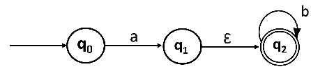
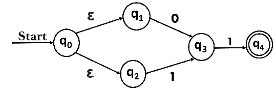
Example:
Convert the following NFA with ε to NFA without ε.Solutions: We will first obtain ε-closures of q0, q1 and q2 as follows:
Now the δ' transition on each input symbol is obtained as:
Now the δ' transition on q1 is obtained as:
The δ' transition on q2 is obtained as:
Now we will summarize all the computed δ' transitions:
The transition table can be:
State q1 and q2 become the final state as ε-closure of q1 and q2 contain the final state q2. The NFA can be shown by the following transition diagram:
NFA and DFA Equivalence
Finite state automata (FSA), also known as finite state machines (FSM), are usually classified as being deterministic (DFA) or non-deterministic (NFA). A deterministic finite state automaton has exactly one transition from every state for each possible input. In other words, whatever state the FSA is in, if it encounters a symbol for which a transition exists, there will be just one transition and obviously as a result, one follow up state. For a given string, the path through a DFA is deterministic since there is no place along the way where the machine would have to choose between more than one transition. Given this definition it isn’t too hard to figure out what an NFA is. Unlike in DFA, it is possible for states in an NFA to have more than one transition per input symbol. Additionally, states in an NFA may have states that don’t require an input symbol at all, transitioning on the empty string ε.Superficially it would appear that deterministic and non-deterministic finite state automata are entirely separate beasts. It turns out, however, that they are equivalent. For any language recognized by an NFA, there exists a DFA that recognizes that language and vice versa. The algorithm to make the conversion from NFA to DFA is relatively simple, even if the resulting DFA is considerably more complex than the original NFA. After the jump I will prove this equivalence and also step through a short example of converting an NFA to an equivalent DFA.
Conversion from NFA to DFA
In this section, we will discuss the method of converting NFA to its equivalent DFA. In NFA, when a specific input is given to the current state, the machine goes to multiple states. It can have zero, one or more than one move on a given input symbol. On the other hand, in DFA, when a specific input is given to the current state, the machine goes to only one state. DFA has only one move on a given input symbol.Let, M = (Q, ∑, δ, q0, F) is an NFA which accepts the language L(M). There should be equivalent DFA denoted by M' = (Q', ∑', q0', δ', F') such that L(M) = L(M').
Steps for converting NFA to DFA:
Step 1: Initially Q' = ϕStep 2: Add q0 of NFA to Q'. Then find the transitions from this start state.
Step 3: In Q', find the possible set of states for each input symbol. If this set of states is not in Q', then add it to Q'.
Step 4: In DFA, the final state will be all the states which contain F(final states of NFA)
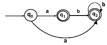
Example 1:
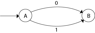
Convert the given NFA to DFA.Solution: For the given transition diagram we will first construct the transition table.
Now we will obtain δ' transition for state q0.
The δ' transition for state q1 is obtained as:
The δ' transition for state q2 is obtained as:
Now we will obtain δ' transition on [q1, q2].
The state [q1, q2] is the final state as well because it contains a final state q2. The transition table for the constructed DFA will be:
The Transition diagram will be:
The state q2 can be eliminated because q2 is an unreachable state.
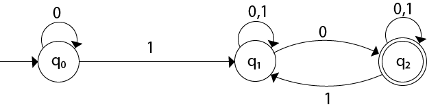
Example 2:
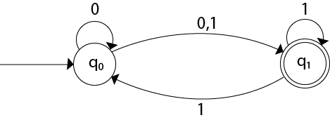
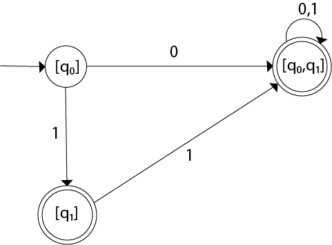
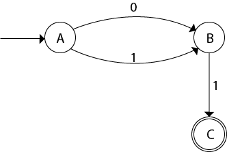
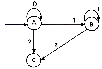
Convert the given NFA to DFA.Solution: For the given transition diagram we will first construct the transition table.
Now we will obtain δ' transition for state q0.
The δ' transition for state q1 is obtained as:
Now we will obtain δ' transition on [q0, q1].
Similarly,
As in the given NFA, q1 is a final state, then in DFA wherever, q1 exists that state becomes a final state. Hence in the DFA, final states are [q1] and [q0, q1]. Therefore set of final states F = {[q1], [q0, q1]}.
The transition table for the constructed DFA will be:
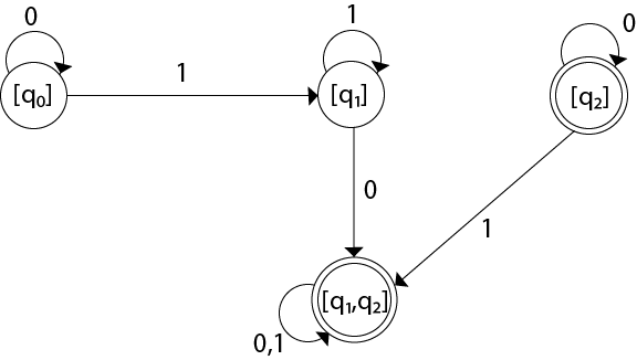
The Transition diagram will be:
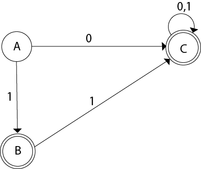
Even we can change the name of the states of DFA.
Suppose
With these new names the DFA will be as follows:
Conversion from NFA with ε to DFA
Non-deterministic finite automata(NFA) is a finite automata where for some cases when a specific input is given to the current state, the machine goes to multiple states or more than 1 states. It can contain ε move. It can be represented as M = { Q, ∑, δ, q0, F}.Where
NFA with ∈ move: If any FA contains ε transaction or move, the finite automata is called NFA with ∈ move.
ε-closure: ε-closure for a given state A means a set of states which can be reached from the state A with only ε(null) move including the state A itself.
Steps for converting NFA with ε to DFA:
Step 1: We will take the ε-closure for the starting state of NFA as a starting state of DFA.Step 2: Find the states for each input symbol that can be traversed from the present. That means the union of transition value and their closures for each state of NFA present in the current state of DFA.
Step 3: If we found a new state, take it as current state and repeat step 2.
Step 4: Repeat Step 2 and Step 3 until there is no new state present in the transition table of DFA.
Step 5: Mark the states of DFA as a final state which contains the final state of NFA.
Example 1:
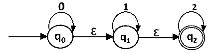
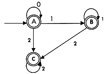
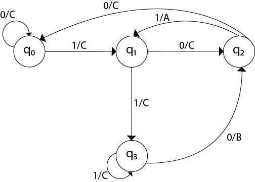
Convert the NFA with ε into its equivalent DFA.Solution:
Let us obtain ε-closure of each state.
Now, let ε-closure {q0} = {q0, q1, q2} be state A.
Hence
The partial DFA will be
Now,
For state C:
The DFA will be,
Example 2:
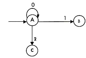
Convert the given NFA into its equivalent DFA.
Solution: Let us obtain the ε-closure of each state.Now we will obtain δ' transition. Let ε-closure(q0) = {q0, q1, q2} call it as state A.
Thus we have obtainedThe partial DFA will be:
Now we will find the transitions on states B and C for each input.
Hence
Thus we have obtainedThe partial transition diagram will be
Now we will obtain transitions for C:
Hence the DFA is
As A = {q0, q1, q2} in which final state q2 lies hence A is final state. B = {q1, q2} in which the state q2 lies hence B is also final state. C = {q2}, the state q2 lies hence C is also a final state.
Minimization of DFA
Minimization of DFA means reducing the number of states from given FA. Thus, we get the FSM(finite state machine) with redundant states after minimizing the FSM.We have to follow the various steps to minimize the DFA. These are as follows:
Step 1: Remove all the states that are unreachable from the initial state via any set of the transition of DFA.
Step 2: Draw the transition table for all pair of states.
Step 3: Now split the transition table into two tables T1 and T2. T1 contains all final states, and T2 contains non-final states.
Step 4: Find similar rows from T1 such that:
That means, find the two states which have the same value of a and b and remove one of them.
Step 5: Repeat step 3 until we find no similar rows available in the transition table T1.
Step 6: Repeat step 3 and step 4 for table T2 also.
Step 7: Now combine the reduced T1 and T2 tables. The combined transition table is the transition table of minimized DFA.
Example:
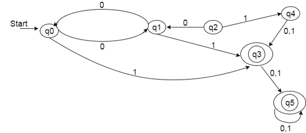
Solution:
Step 1: In the given DFA, q2 and q4 are the unreachable states so remove them.
Step 2: Draw the transition table for the rest of the states.
Step 3: Now divide rows of transition table into two sets as:
1. One set contains those rows, which start from non-final states:
2. Another set contains those rows, which starts from final states.
Step 4: Set 1 has no similar rows so set 1 will be the same.
Step 5: In set 2, row 1 and row 2 are similar since q3 and q5 transit to the same state on 0 and 1. So skip q5 and then replace q5 by q3 in the rest.
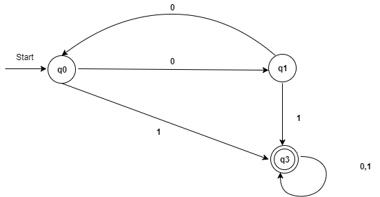
Step 6: Now combine set 1 and set 2 as:
Now it is the transition table of minimized DFA.
Moore Machine
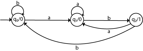
Moore machine is a finite state machine in which the next state is decided by the current state and current input symbol. The output symbol at a given time depends only on the present state of the machine. Moore machine can be described by 6 tuples (Q, q0, ∑, O, δ, λ) where, Example 1:
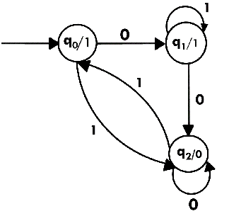
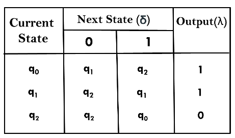
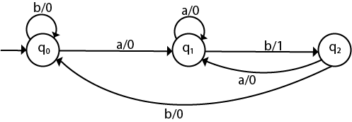
The state diagram for Moore Machine isTransition table for Moore Machine is:
In the above Moore machine, the output is represented with each input state separated by /. The output length for a Moore machine is greater than input by 1.
Input: 010
Transition: δ (q0,0) => δ(q1,1) => δ(q1,0) => q2
Output: 1110(1 for q0, 1 for q1, again 1 for q1, 0 for q2)
Example 2:
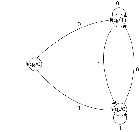
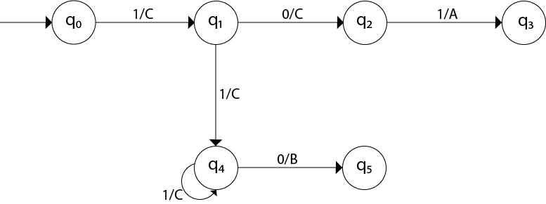
Design a Moore machine to generate 1's complement of a given binary number.Solution: To generate 1's complement of a given binary number the simple logic is that if the input is 0 then the output will be 1 and if the input is 1 then the output will be 0. That means there are three states. One state is start state. The second state is for taking 0's as input and produces output as 1. The third state is for taking 1's as input and producing output as 0.
Hence the Moore machine will be,
For instance, take one binary number 1011 then
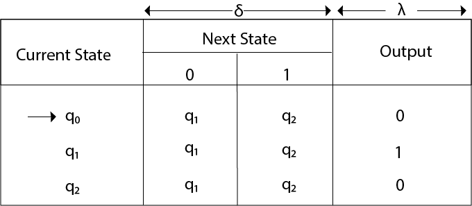
Thus we get 00100 as 1's complement of 1011, we can neglect the initial 0 and the output which we get is 0100 which is 1's complement of 1011. The transaction table is as follows:
Thus Moore machine M = (Q, q0, ∑, O, δ, λ); where Q = {q0, q1, q2}, ∑ = {0, 1}, O = {0, 1}. the transition table shows the δ and λ functions.
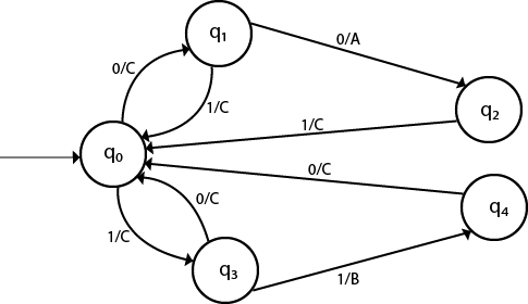
Example 3:
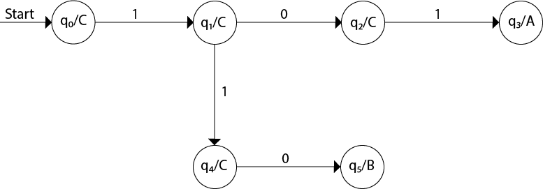
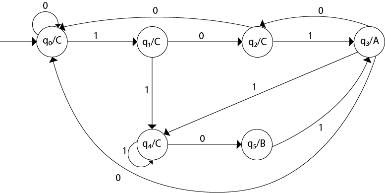
Design a Moore machine for a binary input sequence such that if it has a substring 101, the machine output A, if the input has substring 110, it outputs B otherwise it outputs C.Solution: For designing such a machine, we will check two conditions, and those are 101 and 110. If we get 101, the output will be A, and if we recognize 110, the output will be B. For other strings, the output will be C.
The partial diagram will be:
Now we will insert the possibilities of 0's and 1's for each state. Thus the Moore machine becomes:
Example 4:
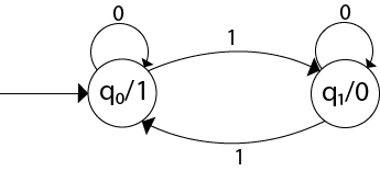
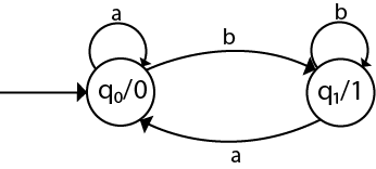
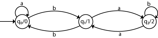
Construct a Moore machine that determines whether an input string contains an even or odd number of 1's. The machine should give 1 as output if an even number of 1's are in the string and 0 otherwise.Solution:
The Moore machine will be:
This is the required Moore machine. In this machine, state q1 accepts
an odd number of 1's and state q0 accepts even number of 1's. There is
no restriction on a number of zeros. Hence for 0 input, self-loop can be
applied on both the states.Example 5:
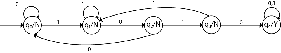
Design a Moore machine with the input alphabet {0, 1} and output alphabet {Y, N} which produces Y as output if input sequence contains 1010 as a substring otherwise, it produces N as output.Solution:
The Moore machine will be:
Mealy Machine
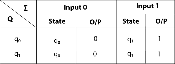
A Mealy machine is a machine in which output symbol depends upon the present input symbol and present state of the machine. In the Mealy machine, the output is represented with each input symbol for each state separated by /. The Mealy machine can be described by 6 tuples (Q, q0, ∑, O, δ, λ') whereExample 1:
Design a Mealy machine for a binary input sequence such that if it has a substring 101, the machine output A, if the input has substring 110, it outputs B otherwise it outputs C.Solution: For designing such a machine, we will check two conditions, and those are 101 and 110. If we get 101, the output will be A. If we recognize 110, the output will be B. For other strings the output will be C.
The partial diagram will be:
Now we will insert the possibilities of 0's and 1's for each state. Thus the Mealy machine becomes:
Example 2:
Design a mealy machine that scans sequence of input of 0 and 1 and generates output 'A' if the input string terminates in 00, output 'B' if the string terminates in 11, and output 'C' otherwise.Solution: The mealy machine will be:
Mealy Machine vs. Moore Machine
The following table highlights the points that differentiate a Mealy Machine from a Moore Machine. Conversion from Mealy machine to Moore Machine
In Moore machine, the output is associated with every state, and in Mealy machine, the output is given along the edge with input symbol. To convert Moore machine to Mealy machine, state output symbols are distributed to input symbol paths. But while converting the Mealy machine to Moore machine, we will create a separate state for every new output symbol and according to incoming and outgoing edges are distributed.The following steps are used for converting Mealy machine to the Moore machine:
Step 1: For each state(Qi), calculate the number of different outputs that are available in the transition table of the Mealy machine.
Step 2: Copy state Qi, if all the outputs of Qi are the same. Break qi into n states as Qin, if it has n distinct outputs where n = 0, 1, 2....
Step 3: If the output of initial state is 0, insert a new initial state at the starting which gives 1 output.
Example 1:
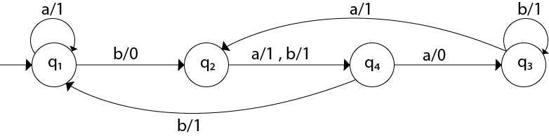
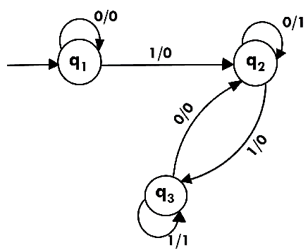
Convert the following Mealy machine into equivalent Moore machine.
Solution:Transition table for above Mealy machine is as follows:
- For state q1, there is only one incident edge with output 0. So, we don't need to split this state in Moore machine.
- For state q2, there is 2 incident edge with output 0 and 1. So, we will split this state into two states q20( state with output 0) and q21(with output 1).
- For state q3, there is 2 incident edge with output 0 and 1. So, we will split this state into two states q30( state with output 0) and q31( state with output 1).
- For state q4, there is only one incident edge with output 0. So, we don't need to split this state in Moore machine.
Transition diagram for Moore machine will be:
Example 2:
Convert the following Mealy machine into equivalent Moore machine.
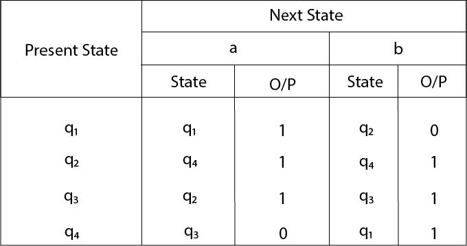
Solution:Transition table for above Mealy machine is as follows:
The state q1 has only one output. The state q2 and q3 have both
output 0 and 1. So we will create two states for these states. For q2,
two states will be q20(with output 0) and q21(with output 1). Similarly,
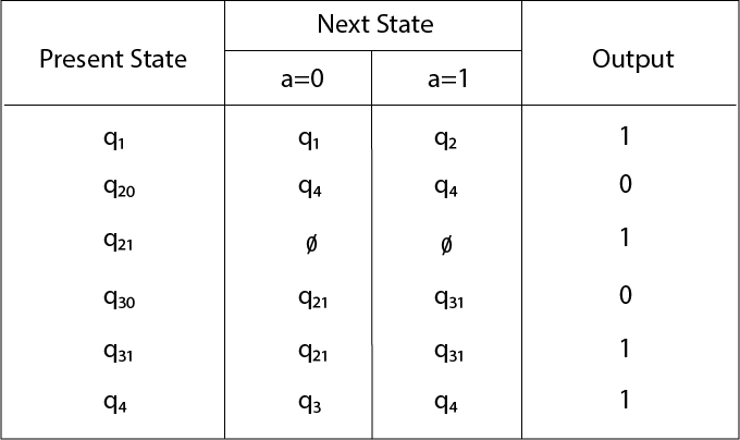
for q3 two states will be q30(with output 0) and q31(with output 1).Transition table for Moore machine will be:
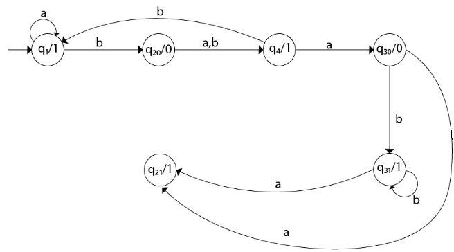
Transition diagram for Moore machine will be:Conversion from Moore machine to Mealy Machine
In the Moore machine, the output is associated with every state, and in the mealy machine, the output is given along the edge with input symbol. The equivalence of the Moore machine and Mealy machine means both the machines generate the same output string for same input string.We cannot directly convert Moore machine to its equivalent Mealy machine because the length of the Moore machine is one longer than the Mealy machine for the given input. To convert Moore machine to Mealy machine, state output symbols are distributed into input symbol paths. We are going to use the following method to convert the Moore machine to Mealy machine.
Method for conversion of Moore machine to Mealy machine
Let M = (Q, ∑, δ, λ, q0) be a Moore machine. The equivalent Mealy machine can be represented by M' = (Q, ∑, δ, λ', q0). The output function λ' can be obtained as:Example 1:
Convert the following Moore machine into its equivalent Mealy machine.Solution:
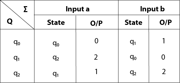
The transition table of given Moore machine is as follows:
The equivalent Mealy machine can be obtained as follows:
Hence the transition table for the Mealy machine can be drawn as follows:
The equivalent Mealy machine will be,
Note: The length of output sequence is 'n+1' in Moore machine and is 'n' in the Mealy machine.
Example 2:
Convert the given Moore machine into its equivalent Mealy machine.Solution:
The transition table of given Moore machine is as follows:
The equivalent Mealy machine can be obtained as follows:
The λ for state q1 is as follows:
The λ for state q2 is as follows:
Hence the transition table for the Mealy machine can be drawn as follows:
The equivalent Mealy machine will be,
Example 3:
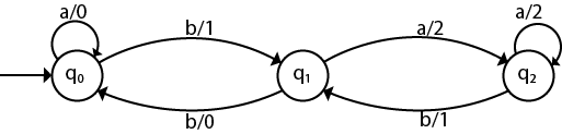
Convert the given Moore machine into its equivalent Mealy machine.Solution:
The transaction diagram for the given problem can be drawn as:
The equivalent Mealy machine can be obtained as follows:
The λ for state q1 is as follows:
The λ for state q2 is as follows:
Hence the transition table for the Mealy machine can be drawn as follows:
The equivalent Mealy machine will be,


0 Comments