
SKYSPIN
In the programmer‘s view of 8085, only the general purpose registers A, B, C, D, E, H, and L, and the Flags registers were discussed so far. But in the complete programmer’s view of 8085, there are two more special purpose registers, each of 16-bit width. They are the stack pointer, SP, and the program counter, PC. The Stack Pointer register will hold the address of the top location of the stack. And the program counter is a register always it will hold the address of the memory location from where the next instruction for execution will have to be fetched. The complete programmer's view of 8085 is shown in the following figure.

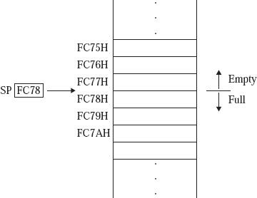
Memory locations FC78H, FC79H, ..., FFFFH are having useful information. In other words, these locations are treated as filled locations. Memory locations FC77H, FC76H, ..., 0000H are not having any useful information. In other words, these locations are treated as empty locations.
On a stack, we can perform two operations. PUSH and POP. In case of PUSH operation, the SP register gets decreased by 2 and new data item used to insert on to the top of the stack. On the other hand, in case of POP operation, the data item will have to be deleted from the top of the stack and the SP register will get increased by the value of 2.
Thus, the contents of SP specify the top most useful location in the stack. In other words, it indicates the memory location with the smallest address having useful information. This is pictorially represented in the following figure –
It is a maskable interrupt, having the lowest priority among all interrupts. It can be disabled by resetting the microprocessor.
When INTR signal goes high, the following events can occur −
Stack and the stack pointer in 8085 Microprocessor
The stack is a LIFO (last in, first out) data structure implemented in the RAM area and is used to store addresses and data when the microprocessor branches to a subroutine. Then the return address used to get pushed on this stack. Also to swap values of two registers and register pairs we use the stack as well.In the programmer‘s view of 8085, only the general purpose registers A, B, C, D, E, H, and L, and the Flags registers were discussed so far. But in the complete programmer’s view of 8085, there are two more special purpose registers, each of 16-bit width. They are the stack pointer, SP, and the program counter, PC. The Stack Pointer register will hold the address of the top location of the stack. And the program counter is a register always it will hold the address of the memory location from where the next instruction for execution will have to be fetched. The complete programmer's view of 8085 is shown in the following figure.
Fig. Programmer's view of 8085
SP
is a special purpose 16-bit register. It contains a memory address.
Suppose SP contents are FC78H, then the 8085 interprets it as follows.Memory locations FC78H, FC79H, ..., FFFFH are having useful information. In other words, these locations are treated as filled locations. Memory locations FC77H, FC76H, ..., 0000H are not having any useful information. In other words, these locations are treated as empty locations.
On a stack, we can perform two operations. PUSH and POP. In case of PUSH operation, the SP register gets decreased by 2 and new data item used to insert on to the top of the stack. On the other hand, in case of POP operation, the data item will have to be deleted from the top of the stack and the SP register will get increased by the value of 2.
Thus, the contents of SP specify the top most useful location in the stack. In other words, it indicates the memory location with the smallest address having useful information. This is pictorially represented in the following figure –
Fig. Interpretation of SP contents
When INTR signal goes high, the following events can occur −
- The microprocessor checks the status of INTR signal during the execution of each instruction.
- When the INTR signal is high, then the microprocessor completes its current instruction and sends active low interrupt acknowledge signal.
- When instructions are received, then the microprocessor saves the address of the next instruction on stack and executes the received instruction.

0 Comments