
SKYSPIN
When microprocessor receives any interrupt signal from
peripheral(s) which are requesting its services, it stops its current
execution and program control is transferred to a sub-routine by
generating CALL signal and after executing sub-routine by generating RET signal again program control is transferred to main program from where it had stopped.
When microprocessor receives interrupt signals, it sends an acknowledgement (INTA) to the peripheral which is requesting for its service.
Interrupts can be classified into various categories based on different parameters:

When microprocessor receives multiple interrupt requests simultaneously, it will execute the interrupt service request (ISR) according to the priority of the interrupts.
Instruction for Interrupts –
In the programmer‘s view of 8085, only the general purpose registers A, B, C, D, E, H, and L, and the Flags registers were discussed so far. But in the complete programmer’s view of 8085, there are two more special purpose registers, each of 16-bit width. They are the stack pointer, SP, and the program counter, PC. The Stack Pointer register will hold the address of the top location of the stack. And the program counter is a register always it will hold the address of the memory location from where the next instruction for execution will have to be fetched. The complete programmer's view of 8085 is shown in the following figure.

Memory locations FC78H, FC79H, ..., FFFFH are having useful information. In other words, these locations are treated as filled locations. Memory locations FC77H, FC76H, ..., 0000H are not having any useful information. In other words, these locations are treated as empty locations.
On a stack, we can perform two operations. PUSH and POP. In case of PUSH operation, the SP register gets decreased by 2 and new data item used to insert on to the top of the stack. On the other hand, in case of POP operation, the data item will have to be deleted from the top of the stack and the SP register will get increased by the value of 2.
Thus, the contents of SP specify the top most useful location in the stack. In other words, it indicates the memory location with the smallest address having useful information. This is pictorially represented in the following figure –
When INTR signal goes high, the following events can occur −
UNIT-2 ( CHAPTER-2 INTERRUPTS AND DATA TRANSFER)
Interrupts in 8085 microprocessor
When microprocessor receives interrupt signals, it sends an acknowledgement (INTA) to the peripheral which is requesting for its service.
Interrupts can be classified into various categories based on different parameters:
- Hardware and Software Interrupts –
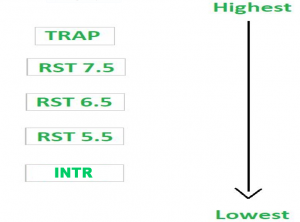
When microprocessors receive interrupt signals through pins (hardware) of microprocessor, they are known as Hardware Interrupts. There are 5 Hardware Interrupts in 8085 microprocessor. They are – INTR, RST 7.5, RST 6.5, RST 5.5, TRAP Software Interrupts are those which are inserted in between the program which means these are mnemonics of microprocessor. There are 8 software interrupts in 8085 microprocessor. They are – RST 0, RST 1, RST 2, RST 3, RST 4, RST 5, RST 6, RST 7.
- Vectored and Non-Vectored Interrupts –
Vectored Interrupts are those which have fixed vector address (starting address of sub-routine) and after executing these, program control is transferred to that address.
Vector Addresses are calculated by the formula 8 * TYPE
- Non-Vectored Interrupts are those in which
vector address is not predefined. The interrupting device gives the
address of sub-routine for these interrupts. INTR is the only non-vectored interrupt in 8085 microprocessor.
- Maskable and Non-Maskable Interrupts –
Maskable Interrupts are those which can be disabled or ignored by the microprocessor. These interrupts are either edge-triggered or level-triggered, so they can be disabled. INTR, RST 7.5, RST 6.5, RST 5.5 are maskable interrupts in 8085 microprocessor. Non-Maskable Interrupts are those which cannot be disabled or ignored by microprocessor. TRAP is a non-maskable interrupt. It consists of both level as well as edge triggering and is used in critical power failure conditions.
When microprocessor receives multiple interrupt requests simultaneously, it will execute the interrupt service request (ISR) according to the priority of the interrupts.
Instruction for Interrupts –
- Enable Interrupt (EI) – The interrupt enable flip-flop is set and all interrupts are enabled following the execution of next instruction followed by EI. No flags are affected. After a system reset, the interrupt enable flip-flop is reset, thus disabling the interrupts. This instruction is necessary to enable the interrupts again (except TRAP).
- Disable Interrupt (DI) – This instruction is used to reset the value of enable flip-flop hence disabling all the interrupts. No flags are affected by this instruction.
- Set Interrupt Mask (SIM) – It is used to implement the
hardware interrupts (RST 7.5, RST 6.5, RST 5.5) by setting various bits
to form masks or generate output data via the Serial Output Data (SOD)
line. First the required value is loaded in accumulator then SIM will
take the bit pattern from it.

- Read Interrupt Mask (RIM) – This instruction is used to read
the status of the hardware interrupts (RST 7.5, RST 6.5, RST 5.5) by
loading into the A register a byte which defines the condition of the
mask bits for the interrupts. It also reads the condition of SID (Serial
Input Data) bit on the microprocessor.

Subroutine in 8085
Unconditional Call instruction –
CALL address is the format for unconditional call instruction. After execution of this instruction program control is transferred to a sub-routine whose starting address is specified in the instruction. Value of PC (Program Counter) is transferred to the memory stack and value of SP (Stack Pointer) is decremented by 2.
Conditional Call instruction –
In these instructions program control is transferred to subroutine and value of PC is pushed into stack only if condition is satisfied.

Unconditional Return instruction –
RET is the instruction used to mark the end of sub-routine. It has no parameter. After execution of this instruction program control is transferred back to main program from where it had stopped. Value of PC (Program Counter) is retrieved from the memory stack and value of SP (Stack Pointer) is incremented by 2.
Conditional Return instruction –
By these instructions program control is transferred back to main program and value of PC is popped from stack only if condition is satisfied. There is no parameter for return instruction.

Advantages of Subroutine –
- Decomposing a complex programming task into simpler steps.
- Reducing duplicate code within a program.
- Enabling reuse of code across multiple programs.
- Improving tractability or makes debugging of a program easy.
Stack and the stack pointer in 8085 Microprocessor
The stack is a LIFO (last in, first out) data structure implemented in the RAM area and is used to store addresses and data when the microprocessor branches to a subroutine. Then the return address used to get pushed on this stack. Also to swap values of two registers and register pairs we use the stack as well.In the programmer‘s view of 8085, only the general purpose registers A, B, C, D, E, H, and L, and the Flags registers were discussed so far. But in the complete programmer’s view of 8085, there are two more special purpose registers, each of 16-bit width. They are the stack pointer, SP, and the program counter, PC. The Stack Pointer register will hold the address of the top location of the stack. And the program counter is a register always it will hold the address of the memory location from where the next instruction for execution will have to be fetched. The complete programmer's view of 8085 is shown in the following figure.
Fig. Programmer's view of 8085
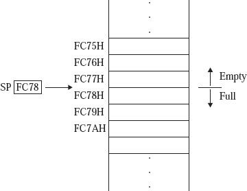
SP
is a special purpose 16-bit register. It contains a memory address.
Suppose SP contents are FC78H, then the 8085 interprets it as follows.Memory locations FC78H, FC79H, ..., FFFFH are having useful information. In other words, these locations are treated as filled locations. Memory locations FC77H, FC76H, ..., 0000H are not having any useful information. In other words, these locations are treated as empty locations.
On a stack, we can perform two operations. PUSH and POP. In case of PUSH operation, the SP register gets decreased by 2 and new data item used to insert on to the top of the stack. On the other hand, in case of POP operation, the data item will have to be deleted from the top of the stack and the SP register will get increased by the value of 2.
Thus, the contents of SP specify the top most useful location in the stack. In other words, it indicates the memory location with the smallest address having useful information. This is pictorially represented in the following figure –
Fig. Interpretation of SP contents
Interrupt Service Routine (ISR)
A small program or a routine that when executed, services the corresponding interrupting source is called an ISR.TRAP
It is a non-maskable interrupt, having the highest priority among all interrupts. Bydefault, it is enabled until it gets acknowledged. In case of failure, it executes as ISR and sends the data to backup memory. This interrupt transfers the control to the location 0024H.RST7.5
It is a maskable interrupt, having the second highest priority among all interrupts. When this interrupt is executed, the processor saves the content of the PC register into the stack and branches to 003CH address.RST 6.5
It is a maskable interrupt, having the third highest priority among all interrupts. When this interrupt is executed, the processor saves the content of the PC register into the stack and branches to 0034H address.RST 5.5
It is a maskable interrupt. When this interrupt is executed, the processor saves the content of the PC register into the stack and branches to 002CH address.INTR
It is a maskable interrupt, having the lowest priority among all interrupts. It can be disabled by resetting the microprocessor.When INTR signal goes high, the following events can occur −
- The microprocessor checks the status of INTR signal during the execution of each instruction.
- When the INTR signal is high, then the microprocessor completes its current instruction and sends active low interrupt acknowledge signal.
- When instructions are received, then the microprocessor saves the address of the next instruction on stack and executes the received instruction.


0 Comments