
SKYSPIN
MOV A 2B (load 2BH in register A)
MOV B 39 (load 39H in register B)
ADD B (A = A + B)
These set of instructions will set the auxiliary carry flag to 1, as on adding 2B and 39, addition of lower order nibbles B and 9 will generate a carry.
4. Parity Flag (P) – If after any arithmetic or logical operation the result has even parity, an even number of 1 bits, the parity register becomes set i.e. 1, otherwise it becomes reset i.e. 0. 1-accumulator has even number of 1 bits
0-accumulator has odd parity
Example:
MVI A 05 (load 05H in register A)
This instruction will set the parity flag to 1 as the BCD code of 05H is 00000101, which contains even number of ones i.e. 2.
5. Carry Flag (CY) – Carry is generated when performing n bit operations and the result is more than n bits, then this flag becomes set i.e. 1, otherwise it becomes reset i.e. 0.
During subtraction (A-B), if A>B it becomes reset and if (A<B) it becomes set.
Carry flag is also called borrow flag. 1-carry out from MSB bit on addition or borrow into MSB bit on subtraction
0-no carry out or borrow into MSB bit
Example:
MVI A 30 (load 30H in register A)
MVI B 40 (load 40H in register B)
SUB B (A = A – B)
These set of instructions will set the carry flag to 1 as 30 – 40 generates a carry/borrow.
MVI A 40 (load 40H in register A)
MVI B 30 (load 30H in register B)
SUB B (A = A – B)
These set of instructions will reset the sign flag to 0 as 40 – 30 does not generate any carry/borrow.
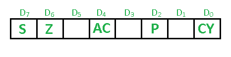
Flag register in 8085 microprocessor
The Flag register is a Special Purpose Register. Depending
upon the value of result after any arithmetic and logical operation the
flag bits become set (1) or reset (0). In 8085 microprocessor, flag
register consists of 8 bits and only 5 of them are useful.
The 5 flags are:- Sign Flag (S) – After any operation if the MSB
(B(7)) of the result is 1, it indicates the number is negative and the
sign flag becomes set, i.e. 1. If the MSB is 0, it indicates the number
is positive and the sign flag becomes reset i.e. 0.
from 00H to 7F, sign flag is 0
from 80H to FF, sign flag is 1 1- MSB is 1 (negative)
0- MSB is 0 (positive)
Example:
MVI A 30 (load 30H in register A)
MVI B 40 (load 40H in register B)
SUB B (A = A – B)
These set of instructions will set the sign flag to 1 as 30 – 40 is a negative number.
MVI A 40 (load 40H in register A)
MVI B 30 (load 30H in register B)
SUB B (A = A – B)
These set of instructions will reset the sign flag to 0 as 40 – 30 is a positive number.
- Zero Flag (Z) – After any arithmetical or logical
operation if the result is 0 (00)H, the zero flag becomes set i.e. 1,
otherwise it becomes reset i.e. 0.
00H zero flag is 1.
from 01H to FFH zero flag is 0 1- zero result
0- non-zero result
Example:
MVI A 10 (load 10H in register A)
SUB A (A = A – A)
These set of instructions will set the zero flag to 1 as 10H – 10H is 00H
- Auxiliary Carry Flag (AC) – This flag is used in
BCD number system(0-9). If after any arithmetic or logical operation
D(3) generates any carry and passes on to B(4) this flag becomes set
i.e. 1, otherwise it becomes reset i.e. 0. This is the only flag
register which is not accessible by the programmer
1-carry out from bit 3 on addition or borrow into bit 3 on subtraction
0-otherwise
MOV A 2B (load 2BH in register A)
MOV B 39 (load 39H in register B)
ADD B (A = A + B)
These set of instructions will set the auxiliary carry flag to 1, as on adding 2B and 39, addition of lower order nibbles B and 9 will generate a carry.
4. Parity Flag (P) – If after any arithmetic or logical operation the result has even parity, an even number of 1 bits, the parity register becomes set i.e. 1, otherwise it becomes reset i.e. 0. 1-accumulator has even number of 1 bits
0-accumulator has odd parity
Example:
MVI A 05 (load 05H in register A)
This instruction will set the parity flag to 1 as the BCD code of 05H is 00000101, which contains even number of ones i.e. 2.
5. Carry Flag (CY) – Carry is generated when performing n bit operations and the result is more than n bits, then this flag becomes set i.e. 1, otherwise it becomes reset i.e. 0.
During subtraction (A-B), if A>B it becomes reset and if (A<B) it becomes set.
Carry flag is also called borrow flag. 1-carry out from MSB bit on addition or borrow into MSB bit on subtraction
0-no carry out or borrow into MSB bit
Example:
MVI A 30 (load 30H in register A)
MVI B 40 (load 40H in register B)
SUB B (A = A – B)
These set of instructions will set the carry flag to 1 as 30 – 40 generates a carry/borrow.
MVI A 40 (load 40H in register A)
MVI B 30 (load 30H in register B)
SUB B (A = A – B)
These set of instructions will reset the sign flag to 0 as 40 – 30 does not generate any carry/borrow.


0 Comments